In our daily life, we will come into contact with a variety of remote controls, television, air conditioning, set-top boxes, etc. There are special remote controls, and many smart phones also support infrared remote control in software and hardware, which can centralize the remote control of most of the household appliances. This article introduces the principle and application of infrared remote control, through the infrared remote control Uno board LED lights.
Infrared remote control principle
Infrared remote control is mainly composed of two parts: infrared transmission and infrared reception.
Infrared transmission and reception of the signal is actually a series of binary pulse code, high and low levels in accordance with a certain time law change to convey the corresponding information. In order to make it free from other signal interference in the wireless transmission process, the signal is usually modulated on a specific carrier frequency (38K infrared carrier signal), through the infrared transmitter diode to transmit out, while the infrared receiving end to demodulate the signal processing, reduced to a binary pulse code for processing.

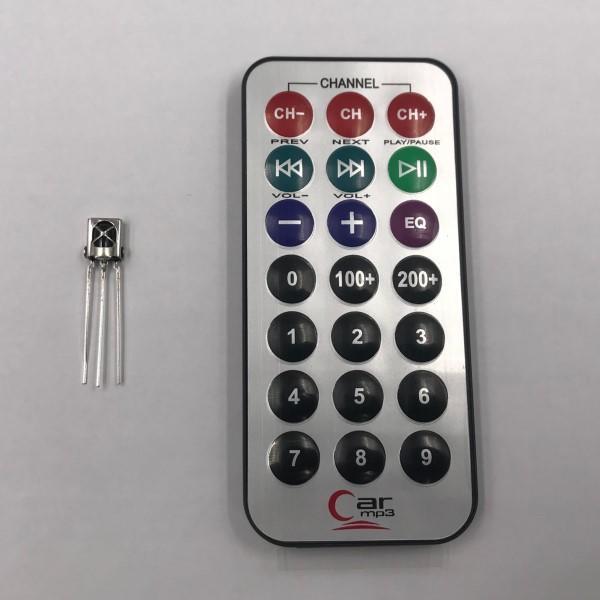
Infrared receiver has three pins, as shown in the above figure from left to right for VOUT, GND, VCC. 38K infrared carrier signals emitted by the remote control by the remote control in the coding chip to encode, the specific coding methods and protocols can be obtained on the Internet, and will not be expanded here. When the remote control button is pressed, the remote control sends out an infrared carrier signal, the infrared receiver receives the signal, and the program decodes the carrier signal, and determines which key is pressed by the difference of the data code.
Infrared Remote Control Library Installation
Click “Project” - “Load Library” - “Manage Library” in IDE, and look for “IRremote” to install.
Experimental Materials
Uno R3 development board
USB cable
Breadboard and cable
Infrared receiver
Infrared remote control
4. Experimental steps
1. Build the circuit according to the schematic diagram.
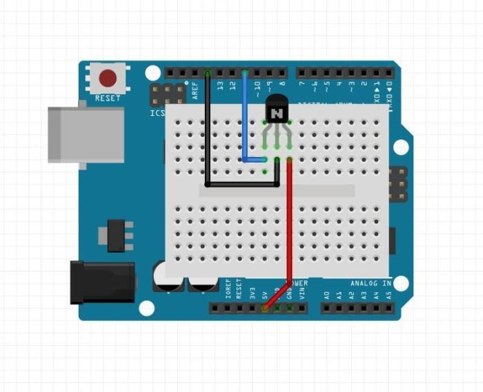
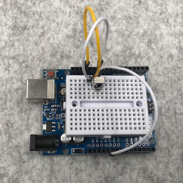
VOUT on the left side of the IR receiver header is connected to digital pin 11 of the development board, and GND and VCC are connected to GND and 5V of the development board respectively.
The experimental schematic diagram is shown below:

The physical connection diagram is shown below:

2. Create a new sketch, copy the following code to replace the automatically generated code and save it.
|
1
2
3
4
5
6
7
8
9
10
11
12
13
14
15
16
17
18
19
20
21
22
23
24
25
26
27
28
29
30
31
32
33
34
35
36
|
/* * IRrecvDemo
* Infrared control, receive infrared commands to control the on-board LED lights on and off
*/
#include <IRremote.h>int RECV_PIN = 11;
int LED_PIN = 13;
IRrecv irrecv(RECV_PIN);decode_results results;void setup()
{ Serial.begin(9600);
irrecv.enableIRIn(); // Start the receiver
pinMode(LED_PIN, OUTPUT);
digitalWrite(LED_PIN, HIGH);
}void loop() {
if (irrecv.decode(&results)) {
Serial.println(results.value, HEX);
if (results.value == 0xFFA25D) //turn on the light value
{
digitalWrite(LED_PIN, LOW);
} else if (results.value == 0xFF629D) //turn off the light value
{
digitalWrite(LED_PIN, HIGH);
}
irrecv.resume(); // Receive the next value
}
delay(100);
} |
3. Connect the development board, set the corresponding port number and board type, and download the program.
Experimental Analysis
The IRremote library is introduced in the program, when the IR remote control is pressed, the key codes of different keys can be seen in the serial monitor, then we selected two key code values for conditional control, and then we can realize the remote control of LED lights.
