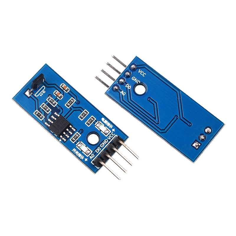
First. Hall Sensor
When a piece of metal or semiconductor sheet with current is placed perpendicularly in a magnetic field, the two ends of the sheet will produce a potential difference, a phenomenon known as the Hall effect. Hall switch is the use of the Hall effect of a sensor, it can be easily converted to magnetic signals into electrical signals, with high reliability and sensitivity.
The sensor uses the M44 switching Hall sensor:

Wiring Instructions:
1.VCC-Positive terminal of power supply
2.GND-Power negative
3.D0-TTL digital output 0 or 1
4.A0-Analog output (different distance output different voltage)
The module has 2 outputs:
1, AO, Hall real-time output Analog output
2、DO, Hall signal after the comparator adjustment output Digital output
VCC: connected to the positive pole of the power supply 3.3-5V
GND: connected to the negative pole of the power supply
DO: module digital signal output, magnetic induction is output low level
AO: Hall real-time voltage output
Second, the code
Magnetic field detection analog signal to test the Hall components can sense the strength of the magnetic field.
Link the analog port to Analog Pin A0
Hold the Hall module, different distances near the speaker (S pole)
|
1
2
3
4
5
6
7
8
9
10
11
12
13
14
|
int sensorVoice = 2;
void setup()
{ pinMode(sensorVoice, INPUT);
Serial.begin(9600);
}void loop()
{ int temp = digitalRead(sensorVoice);
Serial.println(temp);
delay(200);
} |

